The human torpedoes
by
Phil Nussle
The Birth Of An Idea
In the last war Britain’s inventiveness through both necessity and desperation was often quite brilliant though often hampered by petty bureaucracy and ignorance in high office together with a lack of funding. This situation paved the way for lateral thinkers with an abundance of determination to improvise with whatever means they had at their disposal. Events also meant utilising the ingenuity and equipment captured from the opposition. On the night of December 18th 1941, three crews of Italian frogmen sitting astride low speed electrically powered "torpedoes" entered the harbour of Alexandria, Egypt, to deliver their explosive warheads to the British Fleet anchored within. The success of such a daring and ingenious exercise was rewarded with the sinking of the Battleships Queen Elizabeth and Valliant amounting to a total loss of 64,000 tons. This loss impressed neither Churchill or the Admiralty who demanded an immediate response to this form of attack by strengthening boom defences and exercising frequent hull inspections throughout the Mediterranean Fleet. The Admiralty was however impressed by the method in which the attack was carried out and set forth under Churchill’s directive to establish a counterpart for the Royal Navy. To understand this novel method of submersible attack we need to go back to its beginnings. During the First World War the concept of using a torpedo shaped diver delivery vehicle in modified form in order to deliver an explosive charge to ships of the Austrian navy was primarily the brainchild of one Major Raffaele Rossetti, an Italian Naval Engineer, who developed an idea to modify the concept of the torpedo using compressed air as the propulsion system. This afforded an output of 40 h.p. at a constant speed of around 4 knots for a range of eight to ten miles, depending on sea conditions and the status of available compressed air on board. On the 31st. of October, 1918, Rossetti, accompanied by his colleague and fellow designer Sub Lieutenant Raffaele Paolucci, set out from Venice on the torpedo boat 65 PN and headed for the mouth of Pola harbour on the Istrian peninsula (now Croatia). After encountering considerable difficulties with strong currents and the harbours defences they eventually broke through and succeeded in placing the warhead onto the keel of the Austrian battleship Viribus Unitis, which blew up and sank the following morning.
|
|
|
British Mk1 in typical surface approach attitude Prior to reaching
close to the target the chariot was trimmed for surface mode where most of the
journey was spent. |
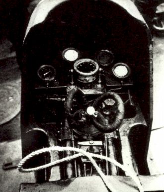
The concept was re-vitalised when Italy joined the war against Britain and France in 1939. The Italian navy was no match for the task ahead and once again through the efforts, ingenuity and dedication of two naval Sub-Lieutenants, Teseo Tesei and Elios Toschi; a much-modified version was produced as a primary form of stealth attack upon a fleet at anchor. This prototype initially utilised an electric motor from a demolished lift as a powerplant delivering the turning motion through a single shaft mounted in the tail cone to the propeller. Energy for the motor was produced using a 30 cell accumulator battery mounted along the floor of the main body of the torpedo and separated by a bulkhead at each end where the trim tanks were housed. The weight of the accumulator pack, together with an electric pump and control box, kept the centre of gravity low which helped to offset any tendency to roll over when the operators were on board. A problem that became obvious in the early stages of development for both the Italians and, later on, with the Royal Navies experimental counterpart. Buoyancy control was achieved using trim tanks within the forward and aft sections of the main body tube and were manipulated by means of two valves, one mounted on either side of the control yoke, by the forward operator. On the surface these tanks were blown or trimmed using an electrically driven pump. The main ballast tank was mounted as a separate unit and was located between the front and rear operator. By blowing or venting this tank by means of a compressed air reservoir the rear operator could control both the sink or rise mode of operation. While in forward motion the front operator used a control yoke, similar in shape to those found in aircraft (fig.1) to control both the diving and ascending attitude by pushing forward or pulling back on the yoke to operate the hydroplane, or by turning the yoke left or right to operate the rudder. Both control surfaces were mounted to the rear of the propeller guard in order to enhance their effect from the propeller stream and linked to the control yoke by cables fed through tubes running the length of the upper body of the torpedo. Speed was adjusted by means of a throttle lever situated between the knees of the forward operator and attached by a cable loop, via pulleys, to a rheostat built into the top of the motor compartment. By turning the lever from the forward neutral position to the left an increase in speed could be achieved, by turning the lever to aft polarity was reversed via a control box, which in turn reversed the rotation of the propeller.
|
|
|
Control Panel Showing control
yoke and motor control lever (below centre). Instruments are compass (centre),
pressure and depth Gauges. |
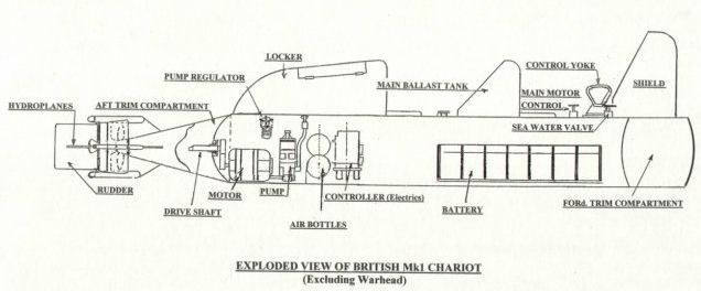
Finally, to the upper aft section, behind the rear operator, a locker box was fixed. This was to contain all the necessary items of equipment for cutting and lifting anti submarine nets that guarded a harbours entrance and acted as a magazine for storing limpets. The torpedo had by now taken on all the characteristics of a miniature submarine but, instead of lying prone as with the original, both operators now sat upright astride the main body protected from the oncoming water stream by a deflective shield. It was soon to be nicknamed the "Maiale", or pig because of its handling characteristics. In the following diagram details of a British Mk1 can be seen in this exploded view. The characteristics are very similar to the Italian original.
|
|
|
|
Upon final acceptance by the Naval authorities a removable warhead containing 300kg of explosive was to be attached to the forward bulkhead. The Italian Navy adopted the new weapon and in 1936 a new arm of the navy was formed at La Spezia that was to become renowned as the 10th. Light Flotilla. Outside of the submarine theatre, underwater warfare now took on a new meaning and Britain felt an urgent need to get involved. The silent removal of both Valliant and Queen Elizabeth prompted an investigation into the construction and use of manned torpedos as a means to deliver an explosive charge against enemy shipping and this in turn obviated the need to develop lightweight diving apparatus in order to function independently over long periods of submersion. Committees were set up within the department of the Admiralty in order to delegate the tasks to those with the best understanding of the aim and it’s final development. With only captured parts to go by in the early stages this fell on the shoulders of a young Naval Commander by the name of ‘Tiny’ Fell with the aid of a fellow colleague, Commander Geoffrey Sladen. Tiny Fell and Geoff Sladen had overall control of development in the initial stages utilising a log as the main body of the vehicle. This had a two gallon tank fixed at both ends adjoined by pipe work fed by a semi-rotary pump with buoyancy and trim controlled by valves, thus copying the functions of a submarine in diluted form. Now, mounting a log some two feet in diameter while treading water may have been easy for a blindfolded lumberjack but it became apparent that the keel needed a considerable amount of weight to be added in order to keep the centre of gravity low while increasing displacement allowing the extra weight of two operators to climb on board keeping more or less upright. This was achieved by screwing lead ballast weights to the underside and helped to prevent tears from forming in the eyes of those present trying to keep a straight face in the previous trial. In 1942 the go ahead was given to produce a prototype that was to become the MK1 and the Royal Navies first attempt to join the special operations underwater theatre of war under the command of the newly formed 12th. Submarine Flotilla.
In The Meantime
Throughout the design and development stage of this form of manned transport men had to be picked for the task of operating the vehicle in all manner of situations and weather conditions predicted only by the final event. In Britain diving equipment had evolved little further than that of the Navies Standard Diving Dress made exclusively by Siebe, Gorman & Company Ltd., and of no use whatsoever for the purpose of autonomous long range diving planned for chariot operations. It is perhaps ironic that Siebe had in fact produced a bubble free rebreather system for autonomous diving called the Amphibian. It was based on the "Salvus" set but utilising a flexible counterlung for re-circulating oxygen. The British Admiralty as having no specific clandestine use turned this down. Siebe offered the design to the Italian navy who accepted its potential and a facility was set up by Siebe in Italy in order to manufacture the units. Consequently modified versions were used by swimmers of the 10th Light Flotilla on their attacks on the British fleet. However salvation came in the form of the D.S.E.A. or Davies Submerged Escape Apparatus. Designed by Robert H. Davis (later to become Sir Robert H. Davis, the Managing Director of Siebe Gorman & Co. Ltd.), specifically for submarine crew as a means of breathing within a stricken submarine while flooding the escape chamber before exit to the surface. This apparatus had a somewhat limited duration for prolonged submersion and it should perhaps be explained how these work to those who are unfamiliar with simple closed circuit breathing units. A simple oxygen closed circuit breathing system recycles oxygen back into a breathing loop by removing carbon dioxide from the exhaled gas via a filter. The term closed circuit simply means that no gas is vented from the system producing bubbles. Ideal solutions preventing any tell tale signatures on the surface in secret operations. The apparatus itself was quite simple and based on systems for use in mine rescue work, mentioned earlier as the "Salvus" set. Designed originally by Henry A. Fleuss and manufactured by Siebe. The D.S.E.A. version consisted of a "U" shaped bag (counter lung) made of rubberised fabric and worn on the chest by means of a neck strap and waist belt. Within the bag a metal canister of tinned mesh containing soda- lime granules was fixed (filter). To this was attached, by means of a waterproof joint, one length of corrugated rubber tube for breathing (pendulum hose). The other end of this tube being attached to a surface cock, this was simply a lever turning a two-way valve that could be opened to ambient air at the surface or straight through to the breathing circuit, this in turn was adjoined to a rubber mouthpiece. Prior to entering the escape chamber the crew member would purge the counter lung with oxygen by cracking the valve open on a small O2 cylinder attached to the inside of the counter lung itself. He would then don a pair of goggles and a nose clip and enter the chamber while breathing from the unit before flooding the chamber. The mode of operation was thus: Upon each exhalation the expired air passed through the soda-lime filter where carbon dioxide was absorbed before entering into the counter lung to be mixed with pure oxygen. Upon inhalation the oxygen again entered through the filter in order to pass back up through the breathing hose and into the lungs in purified form. Upon exit from the escape chamber and, in order to arrest a rapid ascent, the submariner would unroll an apron from the underside of the counter lung and hold this out in front to act as a drag. To prevent embolism through gas expansion while rising from often considerable depths crewmembers were taught always to breath out, not in, at a constant rate as part of their drill. Gas also expanded rapidly within the counter lung as the ambient pressure decreased so an over pressure valve was installed at the top of the counter lung to prevent it from rupturing.
|
|
|
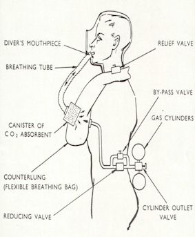
Closed-circuit breathing apparatus |
The action of breathing by means of a single hose when used in a closed circuit rebreather is known as pendulum motion but this was to have two distinct disadvantages when finally adapted for prolonged submersion. Although these sets were used successfully for shallow water clearance diving, it was prone to the build-up of CO2 within the hose and it allowed moisture from exhaled air to run down into the absorbent producing a toxic cocktail capable of causing serious acid burns to the throat and lungs of its user. In order to utilise this apparatus then for any tasks of prolonged duration where a considerable amount of physical effort was to be involved meant a number of modifications had to be made. The first of which was to increase the volume of the filter and to afford accessibility by mounting the filling plate to the front of the counter lung attached to which was an extended breathing tube. In order to prevent water ingress into the breathing tube trials were conducted utilising a full-face mask assembly from the latest version of the "Salvus" set (later to be manufactured as the standard war issue gas mask,) and to this the other end of the breathing tube was attached. Finally with the addition of two back mounted high-pressure cylinders (commandeered from downed German aircraft as the most conveniently suitable lightweight high pressure cylinders available at that time,) and connected to the counter lung via both the reducing and by-pass valves, mounted at the right side of the operator, the navies first dedicated diver rebreather was born.
|
|
|
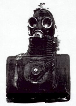
The Siebe Gorman Diver Rebreather This early model
is shown with the Salvus mask and is almost identical to the |